Shutter Speed Testing
Tips and Trix for Amateurs
by Göran Årelind
Working with old, vintage cameras can be both very
interesting and also challenging. In order to conduct an accurate test of
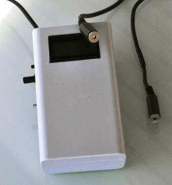
shutter speeds, I bought a shutter tester on eBay. The tester itself is quite
simple, accurate and not too expensive, below US$100, including the required
light source. I recommend buying the light source, it’s rather hard to find a
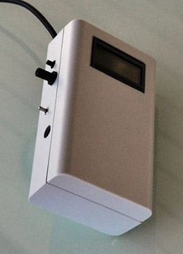
good one. The delivered one has a good intensity that can be adjusted with a potentiometer
on the tester (big black knob on the side). Another advantage with this tester
is that you get the results in decimal form AND in fractions of a second
reading, 1/10, 1/50 etc. To sum up – it’s a fair price for an amateur! The
email address of the supplier I selected is shuttertester@gmail.com. He has a wide range of testers, ask advice about which one best meets your
requirements.
The real challenge occurred when it came to set up the
tests – how to line-up the transmitter and receiver (one LED and one
Photo-Cell) properly? The test results are very much dependent on this part. If
they are not accurately aligned through the axis of the shutter, one in front
of the shutter, the other behind, results will be poor. I’m lucky as I work
with just a few different brands of TLR cameras and they are very similar to
each other so I can “invent” something suitable for all my cameras.
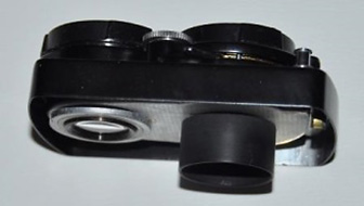
You don’t need to disassemble the camera for testing. However,
to illustrate the set up more clearly, I have used the focusing lensboard
assembly from a Yashica 635, complete with shutter and all covers. The left
lens is the viewing (top) lens and the right lens is the taking (bottom) lens.
On most TLR cameras, there will be a tube fitted to the rear of the taking lens
assembly to provide additional light sealing as the lensboard is moved in and
out during focusing.
Step 1
I made an adapter that will fit into the tube to hold
the receiver for the shutter tester – the images below show what it looks like.
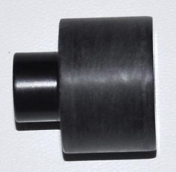
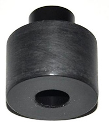
I used a polymer material called POM, also known as acetal or Delrin. This is strong,
but rather easy to work with. It's similar to nylon but harder. It is easy to
machine, a bit like brass. For this and the other parts, I used a lathe. I
guess that you can get POM in most hardware supply stores. It comes in many
different styles, for this part I used a 35 mm rod. Of course, you can use any
material that you can work with.
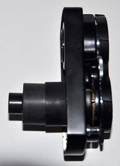
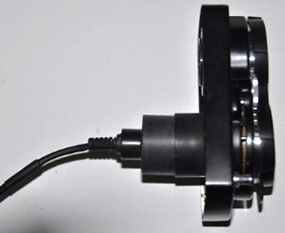
Step 2
The next two pictures show the adapter mounted inside
the tube and finally, with the receiver mounted to the adapter. Be careful to
not push the adapter too deep – that’s not necessary and could damage the rear
lens element. The “inside” of the camera is now ready.
Step 3
The next step is to set up the transmitter in front of
the shutter, which in practical terms means in front of the taking lens (unless
there has been more dismantling). Most TLR cameras have either a bayonet fitting
for filters and lens hoods, or for older and/or more basic versions, a plain
ring for attaching filters and hoods.
I used an old lens hood with Bay I mount for this
first prototype. This fits the majority of Yashicaflex
and Yashicas TLRs from 1954 onwards; many other TLRs; most Rolleicords,
except very early versions, and most Rolleiflexes with
f/3.5 lenses, except very early versions. Of course, a similar adapter could be
made for Rolleiflexes with f/2.8 lenses requiring
either Bay 2 or Bay 3 mount lens hoods, depending on the lens.
Here are a few pictures of the lens hood based front
transmitter adapter.
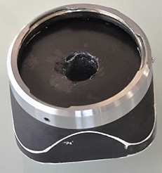
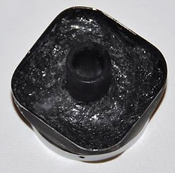
I made a plastic “washer” and placed it in the bottom
of the hood. Be careful – there is a spring loaded ring inside the hood that
must operate freely (pic. 1).
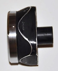
On the washer, I fixed a short tube with the inner diameter fitting the
transmitter perfectly. The whole hood was then filled with epoxy resin
guaranteeing that the pipe and washer will not come loose (pic. 2).
Pic. 3 shows the final
result.
We now have two adapters guiding the transmitter and
receiver in almost perfect alignment and there is very small risk for any
stray-light to interfere with the measurements.
Step 4
The full set-up is shown below.
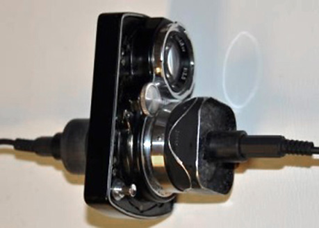
Good luck with your tests!!